Attempt 1

 When I first saw the model, I thought maybe
if I just used a plane, I could not only extrude out the plane faces, I can
also have control on the amount of edges I use. The shape looks accurate
comparing it to the spear tip model and so I extruded out the plane to make it
3-Dimensional. I then deleted the faces that are bevelled inward because I
thought I could extrude and change the edges position to make a nice slope.
When I first saw the model, I thought maybe
if I just used a plane, I could not only extrude out the plane faces, I can
also have control on the amount of edges I use. The shape looks accurate
comparing it to the spear tip model and so I extruded out the plane to make it
3-Dimensional. I then deleted the faces that are bevelled inward because I
thought I could extrude and change the edges position to make a nice slope.When I was about to extrude though, I realised that while the front and side view looks the same, the model is actually a little round and not cubed. The top view is completely different from the spear tip top view. This would require me moving the vertices of the model and mess the model completely. What would be better is if I used a cylinder instead of a plane so I can keep the spear rounded on the top and bottom. Also, the plane does not provided depth which the spear tip model has. All in all, while this was able to maintain its shape from the front and the side, it does not from the top as well as not have any depth present.
 For this attempt, I thought I could try
using the same method on my first attempt but make an outline of the side view.
The first attempt was too flat however, if I started on the side and work my
way inward, I can get the 3D aspect of the spear tip. I got a cylinder and
rotated it and begin with the very tip of the model because the spear tip has a
curved tip which looks like its curved over. I then deleted all but four faces
just to get only the outline of the tip of the spear. This is so later on, I can
just make the outline of the spear tip without worrying about making it 3-Dimensional
unlike my last attempt, I only focused on getting the shape of the tip accurate.
Once I got the outline of the spear tip, I started extruding inward.
Furthermore, I extruded down the middle so I can later on use the multi-cut
tool and make edges. The only issue with is technique is that the topology in
my opinion does not look right. If I want to add an extra edge around
an edge border, it will go around the whole model and make it too sharp compared
to the spear tip.
For this attempt, I thought I could try
using the same method on my first attempt but make an outline of the side view.
The first attempt was too flat however, if I started on the side and work my
way inward, I can get the 3D aspect of the spear tip. I got a cylinder and
rotated it and begin with the very tip of the model because the spear tip has a
curved tip which looks like its curved over. I then deleted all but four faces
just to get only the outline of the tip of the spear. This is so later on, I can
just make the outline of the spear tip without worrying about making it 3-Dimensional
unlike my last attempt, I only focused on getting the shape of the tip accurate.
Once I got the outline of the spear tip, I started extruding inward.
Furthermore, I extruded down the middle so I can later on use the multi-cut
tool and make edges. The only issue with is technique is that the topology in
my opinion does not look right. If I want to add an extra edge around
an edge border, it will go around the whole model and make it too sharp compared
to the spear tip. 
 I thought later on I can fix it later since
I want to mainly focus on getting the shape of the model correct. So, I then used
the bridge command to bridge two edges one by one while going down the model.
As I was bridging, I realised there are too many edges on certain points which make
the whole shape of the model. If I removed an edge loop, then the shape will be
distorted. This attempt while it got the 3D aspect of the spear tip, the topology
and methods I used were not good. While it was quick just to make an outline
and extrude in, the topology needed for other elements such as the rims and the
grooves were not presented well. In addition, on the side view, the spear does
not have any bevelling or depth compared to the spear tip model. For my next
attempt, I will use the cylinder again but not to make the outline. The reason
why I am using a cylinder again is because a cylinder is used as the base of
the spear tip.
I thought later on I can fix it later since
I want to mainly focus on getting the shape of the model correct. So, I then used
the bridge command to bridge two edges one by one while going down the model.
As I was bridging, I realised there are too many edges on certain points which make
the whole shape of the model. If I removed an edge loop, then the shape will be
distorted. This attempt while it got the 3D aspect of the spear tip, the topology
and methods I used were not good. While it was quick just to make an outline
and extrude in, the topology needed for other elements such as the rims and the
grooves were not presented well. In addition, on the side view, the spear does
not have any bevelling or depth compared to the spear tip model. For my next
attempt, I will use the cylinder again but not to make the outline. The reason
why I am using a cylinder again is because a cylinder is used as the base of
the spear tip. 
Attempt 3
 So as previously stated from my last
attempt, I will try using a cylinder to make the model since the spear tip has
a cylinder like base down up. I started by using the measurement tools and
implementing my measurements into the workspace. This is so I know the height and
distance between certain parts of the model and where they transit from one
part to the next in a nice slope. I got a cylinder with a sub-division of 12
and started extruding to match the image reference. Why I choose this technique
is so I can make the starting point on when the shape changes and extrude out.
There are 3 shapes I can already see, meaning 3 segments I need to extrude. I
then delete all faces leaving a quarter of the model so I can focus on one side
instead of trying to make all sides symmetrical. I then extrude the middle part
of the component and tried to keep in mind of the amount of edges in the model
so it’s does not end up causing pinching or small dents in the model. I start
off with the middle because it the biggest piece out of the 3 and also, it’s
the point where the spear tip starts to change.
So as previously stated from my last
attempt, I will try using a cylinder to make the model since the spear tip has
a cylinder like base down up. I started by using the measurement tools and
implementing my measurements into the workspace. This is so I know the height and
distance between certain parts of the model and where they transit from one
part to the next in a nice slope. I got a cylinder with a sub-division of 12
and started extruding to match the image reference. Why I choose this technique
is so I can make the starting point on when the shape changes and extrude out.
There are 3 shapes I can already see, meaning 3 segments I need to extrude. I
then delete all faces leaving a quarter of the model so I can focus on one side
instead of trying to make all sides symmetrical. I then extrude the middle part
of the component and tried to keep in mind of the amount of edges in the model
so it’s does not end up causing pinching or small dents in the model. I start
off with the middle because it the biggest piece out of the 3 and also, it’s
the point where the spear tip starts to change. 

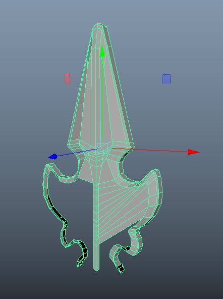
I then repeat the same thing on the bottom curve of the spear tip since this technique worked well from the middle part of the spear tip. Also, this makes the topology of the model have a nice flow. I go back to the top of the component and extrude the faces again to have a nice topology on the model. The then extruded inward but only to make the groove around the top of the spear tip. I was considering to use Boolean just like the bishop model but I thought it was not necessary since this is not a difficult shape to model and while the groove has a little depth, the shape is just a triangle. I finally duplicated the model on the X scale and combine and merge vertices and then repeat for the z scale. Since I wanted that take a look at the finished mode, I need to duplicate all sides. The reason why I remove all by a quarter of the model is so I don’t have to remove the steps and waste time on the other 3 sides.
For the base, I used a cylinder with a
radius of 0.885 because when I measured the base radius, it was 0.885 and
started extruding down. I used the circle curve to set my measurements so I can
C-snap on the curve similar to when I did the base for the bishop model.

 This attempt while the shape is nice, is bottom
of the spear tip is has too many edges also, its pinching and is too sharp
compared to the spear tip where it is more smoother and no bevelling. The outer
rim from the middle and the bottom are too thin and sharp. There is no gradual
slope and it’s too sharp when there should be some roundness. The top also has
no gradual slope from the top of the spear tip to the middle. All in all, the
general shape is ok, but the rim and the groove do not look accurate to the
spear tip. What I should have done was break the model into 3 segments and
using different polygons for each segment. Also, instead of working in the
middle, I should have worked from the top down since the top requires more
edges then the middle and the bottom because the groove is sharp around the
outer edge.
This attempt while the shape is nice, is bottom
of the spear tip is has too many edges also, its pinching and is too sharp
compared to the spear tip where it is more smoother and no bevelling. The outer
rim from the middle and the bottom are too thin and sharp. There is no gradual
slope and it’s too sharp when there should be some roundness. The top also has
no gradual slope from the top of the spear tip to the middle. All in all, the
general shape is ok, but the rim and the groove do not look accurate to the
spear tip. What I should have done was break the model into 3 segments and
using different polygons for each segment. Also, instead of working in the
middle, I should have worked from the top down since the top requires more
edges then the middle and the bottom because the groove is sharp around the
outer edge.
Attempt 4
 As I said on my previous attempt, I will
separate the model into 4 segments because all look and flow differently. To
start with the top, I choose a cube because on the side of the model, its square
a little bit and the top looks like its sloping off, not rounded. I start
extruding down up to the point where its start to slope inward to the middle. I
wanted to focus on getting the shape first and worry about the groove later
because, the groove while it requires more edges, the shape of the model is
important. If the shape does not look like the spear tip, then I would need to
change some edges on both the model as well as the groove which may cause the
groove to distort.
As I said on my previous attempt, I will
separate the model into 4 segments because all look and flow differently. To
start with the top, I choose a cube because on the side of the model, its square
a little bit and the top looks like its sloping off, not rounded. I start
extruding down up to the point where its start to slope inward to the middle. I
wanted to focus on getting the shape first and worry about the groove later
because, the groove while it requires more edges, the shape of the model is
important. If the shape does not look like the spear tip, then I would need to
change some edges on both the model as well as the groove which may cause the
groove to distort. 
 For the middle part, I though instead of
getting another polygon, I can just continue extruding down because if I did
use a cylinder, I would have to bridge both component when I could have just
extruded down and change the position of the vertices as I go. This however
does not work on the bottom as I keep extruding because the spear tip on the
bottom flows different to the middle. So, I had to get a cylinder and rotated
it so the edges are angled and started extruding. I rotated the cylinder so the
topology looks better and also, so I don’t have a lot of edges around the base
of the spear tip. I then had to combine and bridge the two components and fix
the topology so it accurate to the spear tip model.
For the middle part, I though instead of
getting another polygon, I can just continue extruding down because if I did
use a cylinder, I would have to bridge both component when I could have just
extruded down and change the position of the vertices as I go. This however
does not work on the bottom as I keep extruding because the spear tip on the
bottom flows different to the middle. So, I had to get a cylinder and rotated
it so the edges are angled and started extruding. I rotated the cylinder so the
topology looks better and also, so I don’t have a lot of edges around the base
of the spear tip. I then had to combine and bridge the two components and fix
the topology so it accurate to the spear tip model. 
 Out of all 3 attempts, the last one is more
accurate. The only issue is that the rims are too soft and not sharp enough.
Also, on the side view of the model, the middle and bottom does not have a
small bevel compared to the spear tip. Furthermore, the top and middle do not
have the nice slope that slopes down and back up again in order to make the
rim. Similar to my last attempt, while the shape looks accurate, the detail
like the grooves and the rim need more work. I can still use the same method,
but I will start from the bottom and work my way up. I can just use this model
and make a few changes, but it would be much faster if I started on a new model
instead of wasting time trying to fix a small part of the model.
Out of all 3 attempts, the last one is more
accurate. The only issue is that the rims are too soft and not sharp enough.
Also, on the side view of the model, the middle and bottom does not have a
small bevel compared to the spear tip. Furthermore, the top and middle do not
have the nice slope that slopes down and back up again in order to make the
rim. Similar to my last attempt, while the shape looks accurate, the detail
like the grooves and the rim need more work. I can still use the same method,
but I will start from the bottom and work my way up. I can just use this model
and make a few changes, but it would be much faster if I started on a new model
instead of wasting time trying to fix a small part of the model.
In conclusion, while my first attempt was
able to make the shape on the front and the side using just a plane, it does not
show any depth or dimensional compared to my other 2 attempts and the spear
tip. My second attempt on the other hand was able to keep the 3D aspect of the
model, but living the other elements such as the rim, grooves and the topology of
the model does not look good. My third attempt similar to my second attempt it kept
the 3-Dimensional shape of the spear tip, but when it can to making the groove
and the rims, it was either too soft or too sharp. There were no slopes
presents on the rims and no bevelling between the middle and bottom of the
model spear tip. My last attempt however, while it uses a different method, had
a similar result to my second attempt. The rims this time where too soft and
the slope that starts from the top and works its way down the middle isn’t
presented very effectively.


