Attempt 1
When I starting modelling the model, I
thought I follow what Jacqui did with the class last year which was using a
curve to make the dome of the model and then using Boolean to make the grooves
on the model. As I was making the curve, revolving that curve and making it
into a polygon, the model has a lot of N-gons revolved around it. While this
was a fast way to make the shape, I do not have control on the amount of edges
and sub-divisions necessary for the model. It would have been fast and more
effective if I had created either a pipe or a cylinder, that way I can simply
change the sub-division in the input channel box instead of using that time to
delete and remove edges.
Attempt 2
 My next attempt was to experiment with the
polygons provided for me. So, I thought maybe a sphere would work since it has
a smooth curve similar to the dome base of the model. I got a sphere, set its
sub-division to 8 because I want to start off small instead of sticking to the
sphere’s default setting which is 20 since 20 is too dense for this model and
also, if I need more edges, I can add more using the multi-cut tool. If 8
sub-division does not work, I can get another sphere and change it to a higher
value like 12 (trial and error). Next, I change the position of the edge loops
around the sphere to match my measurement from class. I did not change the
transform constraint from off to edge slide because I did not want to alter the
shape. The sphere has a smooth curve which makes the shape have a nice slope.
My next attempt was to experiment with the
polygons provided for me. So, I thought maybe a sphere would work since it has
a smooth curve similar to the dome base of the model. I got a sphere, set its
sub-division to 8 because I want to start off small instead of sticking to the
sphere’s default setting which is 20 since 20 is too dense for this model and
also, if I need more edges, I can add more using the multi-cut tool. If 8
sub-division does not work, I can get another sphere and change it to a higher
value like 12 (trial and error). Next, I change the position of the edge loops
around the sphere to match my measurement from class. I did not change the
transform constraint from off to edge slide because I did not want to alter the
shape. The sphere has a smooth curve which makes the shape have a nice slope.

For the grooves I wanted to try using a
plane and change it shape to match the grooves on the model. This way I can
just extrude to make it 3-Dimensional and maintain the position of edges and
vertices and I also don’t have to terminate any edges. I then used Boolean so I
combine shapes that would be difficult to model. This left a hole in the model
so I had to fill the hole using Fill Hole and use the multi-cut to merge and
create edges. I later made to make all the N-gons around the groove into quads using
the multi-cut tool.

 This attempt while simple was not very
effective. The edges around the groove were making the model shape instead of
curved. Also, the grooves from the top to the bottom is causing this weird
pinching and is also too soft. Even if I added another edge loop around it, it
would make the groove have too many edges. While the sphere made a nice curve
around the dome bottom, it might be more better if I used a cylinder for the
rest of the dome and maybe try using a torus as well for an experiment.
This attempt while simple was not very
effective. The edges around the groove were making the model shape instead of
curved. Also, the grooves from the top to the bottom is causing this weird
pinching and is also too soft. Even if I added another edge loop around it, it
would make the groove have too many edges. While the sphere made a nice curve
around the dome bottom, it might be more better if I used a cylinder for the
rest of the dome and maybe try using a torus as well for an experiment.
Attempt 3
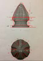
 For this attempt I thought maybe I try using
 multiple polygons instead of using one polygon to make the whole model.
I took some photos of the actual bishop/spear tip and divided it into 3
segments because I want to simplify the shapes from a 3D model to 2D shapes. I
then determine the polygons I can already see so, for the bottom for example, I
can see a cylinder because from the top-view it’s a circle and in the from view
its straight and for the mid, I see the inside of a torus since while Jacqui
demonstrated this model, she used a torus and deleted all the faces except the
middle and reversing the normal. I wanted to initial use a cylinder, but I also
wanted to experiment with use of a torus and see the different between the two.
For sub-division, from my last attempt I used a sub-division of 8 which in my
opinion was too low for this model. I don’t want to make the model too d
ense
since the model is too small. I ended up starting with 16 because if I started
with 12 I cannot add another edge without ruining the shape of the model.
 I used a circle curves to make a structure
and get my radius for each measurement. If I had just used measure tools to add
my radius measurements, then I would not be able to get an understand of
measurement. So, I used curves for my radius and the distance measure tool for
the height. I start to build from the bottom up by creating a cylinder with a
sub-division of 16 as previously mentioned, with a radius of 1.5 (my measurement
from the bishop was 3cm in diameter) and removed the top and bottom faces
leaving the sides because I don’t need them currently and I can easy Fill Hole
and used the multi-cut tool to add the edges back but instead of triangles, I
make then into quads. I also, scaled the height of the cylinder to match the
measurements of my reference. I did not extrude because I want to focus on
getting the shape of the model first then later on add edges or bevel the edge
borders.
I used a circle curves to make a structure
and get my radius for each measurement. If I had just used measure tools to add
my radius measurements, then I would not be able to get an understand of
measurement. So, I used curves for my radius and the distance measure tool for
the height. I start to build from the bottom up by creating a cylinder with a
sub-division of 16 as previously mentioned, with a radius of 1.5 (my measurement
from the bishop was 3cm in diameter) and removed the top and bottom faces
leaving the sides because I don’t need them currently and I can easy Fill Hole
and used the multi-cut tool to add the edges back but instead of triangles, I
make then into quads. I also, scaled the height of the cylinder to match the
measurements of my reference. I did not extrude because I want to focus on
getting the shape of the model first then later on add edges or bevel the edge
borders.
 For the mid -section, I create a torus with
a sub-division of 16 as mentioned before, to experiment if the torus works on
this attempt and has a radius of 1.3. Once happy with the shape, I combined and
bridge both component as well as bevelled the bridge edges to make the bump and
bevel the edge borders from the cylinder. By combining and bridging the
components together, I wanted to see the final shape of the base before
starting with the dome. It ended up looking nicer than my last 2 attempts
because from my first attempt, the curve does not give me much control and for
my second attempt with the sphere, the base is too rounded and soft. So, if I
were to do another attempt if this does not work, I will be using a cylinder
again for the bottom and try to use another cylinder for the mid curve.
Although the torus works nice, I just think it using too many edges just for
that one space.
For the mid -section, I create a torus with
a sub-division of 16 as mentioned before, to experiment if the torus works on
this attempt and has a radius of 1.3. Once happy with the shape, I combined and
bridge both component as well as bevelled the bridge edges to make the bump and
bevel the edge borders from the cylinder. By combining and bridging the
components together, I wanted to see the final shape of the base before
starting with the dome. It ended up looking nicer than my last 2 attempts
because from my first attempt, the curve does not give me much control and for
my second attempt with the sphere, the base is too rounded and soft. So, if I
were to do another attempt if this does not work, I will be using a cylinder
again for the bottom and try to use another cylinder for the mid curve.
Although the torus works nice, I just think it using too many edges just for
that one space.

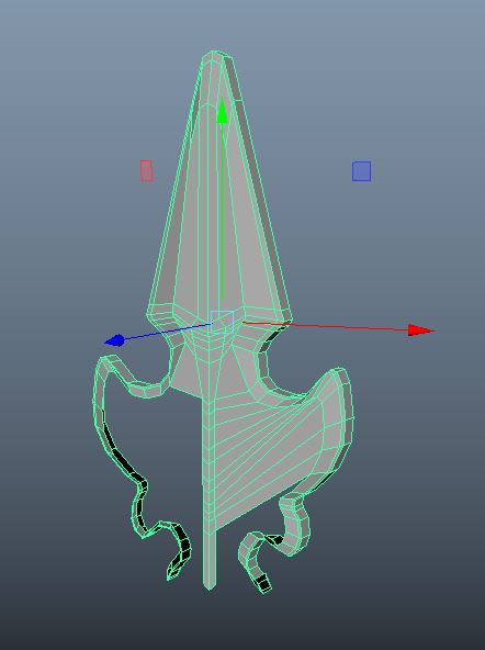
 For the top-section/dome, I used another
cylinder and scaled the cylinder because from my previous attempts, while a
curve can make a more accurate dome, I does not give me a choice on how my
sub-divisions and edges I want. As for the cylinder, I have the option on the
amount of sub-division I need and by using the circle curves, I can C-snap the
edge loop to the curves. I forgot to delete the top and bottom faces of the
cylinder because they were tri faces and I wanted them to be quads which I can
do later. Since Boolean did not work as effective from my last attempt, I thought
I try just deleting the faces that make the groove and extrude inward. This did
not work as well. This made the grooves even softer than using a Boolean. The
top and bottom are way too soft compared to the bishop and my last attempt.
For the top-section/dome, I used another
cylinder and scaled the cylinder because from my previous attempts, while a
curve can make a more accurate dome, I does not give me a choice on how my
sub-divisions and edges I want. As for the cylinder, I have the option on the
amount of sub-division I need and by using the circle curves, I can C-snap the
edge loop to the curves. I forgot to delete the top and bottom faces of the
cylinder because they were tri faces and I wanted them to be quads which I can
do later. Since Boolean did not work as effective from my last attempt, I thought
I try just deleting the faces that make the groove and extrude inward. This did
not work as well. This made the grooves even softer than using a Boolean. The
top and bottom are way too soft compared to the bishop and my last attempt.
 From this attempt, the shape looks much
better so I will be using a cylinder for the dome. Also, as stated before, for
the base, I will be using cylinder, one for the bottom, and one for the mid
curved. For the mid-section, I can get a cylinder and C-snap the cylinder to
the curve and extrude in instead of getting a torus, deleting but the inside
and reversing the normals.
From this attempt, the shape looks much
better so I will be using a cylinder for the dome. Also, as stated before, for
the base, I will be using cylinder, one for the bottom, and one for the mid
curved. For the mid-section, I can get a cylinder and C-snap the cylinder to
the curve and extrude in instead of getting a torus, deleting but the inside
and reversing the normals.
Attempt 4
Since my last attempt worked better than my
first two, I will be doing a similar method with a few changes. I first
divide the object reference but instead of 3, its 4 because the dome has a
curved bottom which would work better with a curve object like a torus or a
sphere instead of a cylinder. I will begin with the dome first instead of the
bottom since it requires more edges compared to the rest. The sub-divisions
will stay the same because it worked effective on my last attempt. If I add
more sub-divisions, I would use more edges then necessary.

 For the dome bottom, I create a torus with
a radius of 1.55 and delete all but the outer middle ring faces. This way I can
keep the curve and not have to change the position of the edges. I then I
created a cylinder and scaled to the match measurements and finally combine the
two components. Although, what I could have done was extruded the edges from
the torus upward instead of using most that time bridging and combing the
components. Furthermore, as mentioned before, from my previous attempt with the
cylinder, it was accuracy with the bishop’s shape and thus I am using the
cylinder again.
For the dome bottom, I create a torus with
a radius of 1.55 and delete all but the outer middle ring faces. This way I can
keep the curve and not have to change the position of the edges. I then I
created a cylinder and scaled to the match measurements and finally combine the
two components. Although, what I could have done was extruded the edges from
the torus upward instead of using most that time bridging and combing the
components. Furthermore, as mentioned before, from my previous attempt with the
cylinder, it was accuracy with the bishop’s shape and thus I am using the
cylinder again.

 For the groove however, I had to use
Boolean again since it helps make difficult shapes easier to model and also,
from my last attempt, removing faces and extruding in do not work very well
compared to using Boolean. So, I just a created a cylinder and scale the edge
borders to match the bishop model grooves and placed the cylinder just outside
the model. The reason I used a cylinder is because the bishop model has some
thin oval grooves which is curved inward just a tiny bit and also, the top is
smaller compared to both the middle and the bottom which look similar but are
slightly different, which is why I had to scale the cylinder a bit. I had to
however, delete a few edges and faces in order to fix the topology and edge
flow of the object. I also had to terminate the edges by making an edge ring
around the groove so it does not ruin the mesh and flow of the model.
For the groove however, I had to use
Boolean again since it helps make difficult shapes easier to model and also,
from my last attempt, removing faces and extruding in do not work very well
compared to using Boolean. So, I just a created a cylinder and scale the edge
borders to match the bishop model grooves and placed the cylinder just outside
the model. The reason I used a cylinder is because the bishop model has some
thin oval grooves which is curved inward just a tiny bit and also, the top is
smaller compared to both the middle and the bottom which look similar but are
slightly different, which is why I had to scale the cylinder a bit. I had to
however, delete a few edges and faces in order to fix the topology and edge
flow of the object. I also had to terminate the edges by making an edge ring
around the groove so it does not ruin the mesh and flow of the model.

For the bottom of the base, I used a
cylinder as previously mentioned with a sub-division of 18 instead of 16
because when I check the amount of edges necessary to bridge, the poly count of
edges said 18 instead of 16. For the mid-section, I wanted to try using a
cylinder instead of a torus to see if there is a difference between using a
cylinder and using a torus. Although the torus from my previous method works, I
had to delete and reverse normals. For the cylinder however, I simply added an
edge using edge ring and split and scale the edge to the curves’ measurement
making this more simpler and more effective than my previous method. When
comparing the torus and the cylinder, I honestly don’t see a difference. The
torus has more edges but, if I deleted them and scaled it a bit more, it would
look just like the cylinder. So, using a cylinder works just as much as using a
torus.
 After that, I combined and bridged the two
objects and bevelled the bridges edges making a small indent. Since I was happy
with how to turned out, I started adding edges and edge loops to sharpen edge
borders and make small details like the small bevelled indent on the base. Once
finished, I deleted all but the groove side because the bishop has a total of 6
grooves around the model and I need to duplicated 2 more models. If I
duplicated 5 instead of 2, it would take longer to combine and merge 5 times.
So, I duplicated 2 models and combined and merge vertices on the 3 components
and repeated for the other side by duplicating and set the X-scale to -1.
After that, I combined and bridged the two
objects and bevelled the bridges edges making a small indent. Since I was happy
with how to turned out, I started adding edges and edge loops to sharpen edge
borders and make small details like the small bevelled indent on the base. Once
finished, I deleted all but the groove side because the bishop has a total of 6
grooves around the model and I need to duplicated 2 more models. If I
duplicated 5 instead of 2, it would take longer to combine and merge 5 times.
So, I duplicated 2 models and combined and merge vertices on the 3 components
and repeated for the other side by duplicating and set the X-scale to -1.
Out of all 4 attempts I did, this attempt
was more effective and more accurate to the bishop model compared to my other 3
attempts. I just need to make a few changes to the groove and make the topology
have a better flow as well as fix the grooves to make it sharper on the sides
and a tiny bit softer on the top and bottom.
In
conclusion, while my first attempt was about to make an accurate shape of the
bishop model, I was not able to have control on the amount of sub-division I
want in a model. In my second attempt, while using a sphere was able to make
the slop of the dome smoother, it would be more better if I used more than one
polygon for the model as well as maybe trying using a cylinder for the base and
part of the dome. For my third attempt, using a cylinder for the base and the
dome looked accurate to the model, deleting a few faces and extruding in does
not work as well as using Boolean. Finally, my last attempt, it matches the
shape however, I still need to edit a bit on the topology as well as fix the
grooves’ size and depth.